

Manual SuperSieve Pump
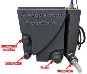
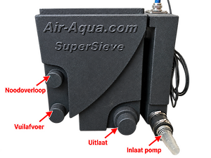
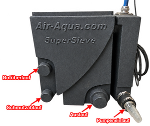
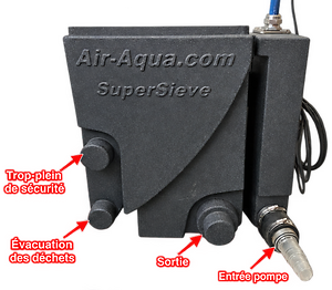
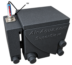
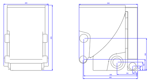
The SuperSieve Pump is a pump-fed pre-filter designed for the mechanical removal of dirt particles from pond water. Water is pumped from the pond to the SuperSieve Pump and then flows through the sieve element. Dirt particles are separated from the water by the sieve element and collected in the waste collection area.
After passing through the sieve element, the water leaves the SuperSieve Pump via the outlets. From this point, the water must always be able to flow away freely, for example to the next filter component or a return point.
1. Installation position
Place the SuperSieve Pump on a stable and completely level surface. There are no specific requirements regarding installation height. When selecting the installation position, make sure there is sufficient space around the SuperSieve for connecting the pipework, cleaning and maintenance.
It is important that the water can flow away freely after leaving the SuperSieve Pump. The outlet pipes must therefore be installed in such a way that the water can flow without obstruction and no unwanted back pressure is created.
2. Connecting the inlet
The SuperSieve Pump housing is manufactured from PE (polyethylene). PVC pipes and fittings therefore cannot be glued directly to the PE connections of the SuperSieve. We recommend using flexible EPDM couplings to connect the pipework. These also allow easy installation and removal.
The SuperSieve Pump has a 63 mm inlet connection for the supply from the pond pump. The inlet can be connected on either the left or right side. Select the side that best suits the pipe layout of the installation.
A 63 mm flexible EPDM coupling and hose tail are supplied as standard for connecting the pond pump. These allow the supply from the pond pump to be connected easily to the SuperSieve Pump.
3. Connecting the outlets
The SuperSieve Pump is equipped with an outlet connection on both sides. These connections are suitable for 75 or 110 mm pipework. Depending on the required pipe diameter, the connection can be cut at the designated position.
Because the housing and connections are manufactured from PE, PVC pipes and fittings cannot be glued directly to the connections. Flexible EPDM couplings are recommended for connecting PVC pipework.
Before cutting, carefully check which diameter will be used and only cut off the section required for the desired connection.
The maximum flow rate of the SuperSieve Pump is 20 m³/hour. To handle this capacity, both 110 mm outlets must be used.
The water must be able to flow away freely after leaving the SuperSieve Pump. Avoid restrictions, unnecessary resistance or other situations that could cause back pressure on the outlet side.
4. Waste drain
The SuperSieve Pump has two 63 mm waste drains, one on each side of the housing. The waste drains are located at the bottom of the waste collection area of the sieve element.
A 63 mm pipe can be connected to the required waste drain. Because the connection is manufactured from PE, we recommend using a flexible EPDM coupling. Install a 63 mm ball valve or slide valve so that the waste drain can be opened and closed easily.
Open the waste drain when the collected dirt needs to be removed from the SuperSieve. If necessary, the dirt can be flushed away with water. Close the ball valve or slide valve completely after cleaning.
5. Sieve element
The SuperSieve Pump is supplied as standard with a 300 micron sieve element. The water supplied by the pump flows through the sieve element, separating dirt particles from the water and collecting them in the waste collection area.
Check the sieve element regularly. The required cleaning frequency depends on the amount and type of dirt being separated from the pond water.
6. Emergency overflow
The SuperSieve Pump is equipped with a 75 mm emergency overflow on both sides. If the emergency overflow is not connected and the sieve element becomes heavily contaminated or blocked, the water level in front of the sieve element will rise. Once the water reaches the top of the sieve element, it flows behind the sieve element and then leaves the SuperSieve through the normal outlets.
Water passing via the emergency overflow does not pass through the sieve element and is therefore not mechanically filtered. If the emergency overflow comes into operation, the sieve element must be checked and cleaned.
7. Commissioning
- Place the SuperSieve Pump on a stable surface and check that it is completely level.
- Check that the inlet, outlets and waste drain are connected correctly.
- Check that all flexible EPDM couplings are installed correctly and that the hose clamps are securely tightened.
- Check that the ball valve or slide valve on the waste drain is closed.
- Check that the sieve element is positioned correctly in the SuperSieve.
- Check that the water can flow freely through the outlet pipes.
- Switch on the pond pump.
- Check the installation for leaks and make sure the water flows correctly over the sieve element.
Do not exceed the maximum capacity of 20 m³/hour. Both 110 mm outlets must be used to achieve this maximum capacity.
8. Cleaning the sieve element
The flow through the sieve element may decrease over time as dirt accumulates. The sieve element should therefore be cleaned regularly.
For thorough cleaning, the sieve element can be removed from the SuperSieve Pump. It can be cleaned using a brush or pressure washer.
During cleaning, also check for limescale deposits. Over time, limescale can accumulate on the surface and in the openings of the sieve element, reducing the flow rate.
If limescale is present, the sieve element can be cleaned using a mild or, if necessary, stronger acid. Use a suitable product for removing limescale and always follow the instructions for use and safety instructions supplied with the cleaning product.
After treatment with acid, always rinse the sieve element thoroughly with clean water before reinstalling it in the SuperSieve Pump.
9. Optional submersible UV-C
The SuperSieve Pump can optionally be equipped with an Air-Aqua submersible UV-C unit. The UV-C unit is installed using a special fitting in the pre-chamber into which the water is supplied by the pond pump.
The UV-C unit is not installed in the lid of the main housing. By installing it in the pre-chamber, the incoming water passes the UV-C unit before flowing to the sieve element. Always install a non-return valve in the inlet pipe when a UV lamp is installed. This prevents the UV lamp from running dry when the pump is switched off, as the water will remain in the pre-chamber.
The SuperSieve Pump is suitable for the designated Air-Aqua 25, 40 and 55 Watt submersible UV-C units.
10. Safety when using UV-C
UV-C radiation can be harmful to the eyes and skin. Always observe the applicable safety instructions when using a submersible UV-C unit.
- Always switch off the UV-C unit before opening the pre-chamber or carrying out work on the SuperSieve Pump.
- Disconnect the plug from the power supply before carrying out any work on the UV-C unit.
- Never look directly at an operating UV-C lamp.
- Avoid exposing the eyes and skin to UV-C radiation.
- Use suitable UV safety glasses when installing, inspecting or maintaining the UV-C lamp.
Suitable UV safety glasses are available from Air-Aqua: UV safety glasses.
11. Periodic maintenance
Check the SuperSieve Pump regularly to maintain proper operation and flow. Pay particular attention to:
- contamination and flow through the sieve element;
- any limescale deposits on the sieve element;
- the waste collection area and waste drain;
- free flow through the outlet pipes;
- the connections and flexible EPDM couplings for any leaks;
- the operation and condition of any installed submersible UV-C unit.
After the pump is switched off, the water drains from the SuperSieve Pump via the bottom. As a result, the housing does not remain filled with water, with the exception of the pre-chamber if a non-return valve has been installed there.
12. Troubleshooting
Water flows via the emergency overflowPossible cause: The sieve element is dirty or blocked.
Solution: Check and clean the sieve element.
Water does not drain sufficientlyPossible cause: Insufficient free discharge or excessive back pressure.
Solution: Check the outlet pipes for restrictions, resistance or blockages.
The required maximum flow rate is not achievedPossible cause: Insufficient outlet capacity.
Solution: Use both 110 mm outlets for a maximum capacity of 20 m³/hour.
Water slides over the sieve element and does not pass through it properlyPossible cause: Dirt or limescale deposits on the sieve element.
Solution: Clean the sieve element and remove any limescale deposits if necessary.
Water does not flow evenly over the sieve elementPossible cause: The SuperSieve Pump may not be level.
Solution: Check the installation and level the SuperSieve completely.
Leakage at a connectionPossible cause: A flexible EPDM coupling is not installed or secured correctly.
Solution: Check the position of the coupling and make sure the hose clamps are securely tightened.
13. Technical specifications
- Type: SuperSieve Pump
- Configuration: pump-fed
- Housing material: PE (polyethylene)
- Standard sieve element: 300 micron
- Pump inlet: 63 mm, left or right
- Outlets: 75/110 mm, left and right
- Waste drain: 63 mm, left and right
- Maximum flow rate: 20 m³/hour when using both 110 mm outlets
- UV-C option: Air-Aqua 25, 40 or 55 Watt submersible UV-C
- Lid: supplied as standard
- Supplied for pump connection: 63 mm flexible EPDM coupling and hose tail
Important points
- Always install the SuperSieve Pump completely level.
- Make sure the water can always flow away freely after the SuperSieve and avoid back pressure.
- Use both 110 mm outlets for a maximum capacity of 20 m³/hour.
- The PE connections cannot be glued directly to PVC pipes and fittings. Flexible EPDM couplings are recommended.
- Check and clean the sieve element if water flows via the emergency overflow.
- Always switch off any installed UV-C unit before opening the pre-chamber or carrying out work on the installation.